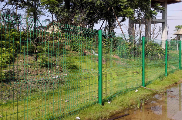
PVC Coated Welded Wire Mesh Fence Single Fabric Widths: 3.0 Meters
We manufacture and sell Welded Wire Mesh Fences with a single fabric system and PVC coated gauge. Our standard panels come in widths of 3.0 meters. In addition to providing high-quality fencing solutions, we also offer engineering design and installation services tailored to meet our customers' specific needs. We specify the production and installation standards for your reference, showcasing our ability to customize solutions that fit your requirements perfectly.
Scope and References
This specification covers materials, accessories, and installation for a complete galvanized welded wire mesh fence system, including gates.
Referenced ASTM Standards:
- A307: Carbon Steel Bolts and Studs, 60,000 PSI Tensile (414 MPa)
- A853: Steel Wire, Carbon, for General Use
- C94: Ready-Mix Concrete
- F567: Installation of Chain Link Fence
- F626: Fence Fittings
- F900: Industrial and Commercial Swing Gates
- F1043: Strength and Protective Coatings on Metal Industrial Chain Link Fence
- F1916: Selecting Chain Link Barrier Systems with Coated Chain Link Fence Fabric and Round Posts for Detention Applications (Grounding reference only).
Welded Wire Mesh Fence Products
This welded wire mesh fence system is designed to offer a durable, customizable solution for perimeter security. The materials used in its construction meet rigorous standards to ensure strength, stability, and long-lasting performance. The posts are made from high-quality materials that comply with ASTM specifications, while the welded wire fabric is reinforced with both galvanization and PVC coating for enhanced corrosion resistance. The fabric heights and panel sizes are flexible, allowing for customization based on specific project requirements. Below is a detailed breakdown of the materials used in the system.
- Posts: The posts for the fence must meet ASTM F1043 standards, with yield strength and section modulus that comply with or exceed ASTM F1083 pipe requirements. This ensures the posts have the necessary structural integrity to support the fence system.
- Welded Wire Fabric: The fabric is made from electronically welded low-carbon steel wire, forming the specified mesh pattern. The wire used is of ASTM A853, Grade AISI 1006, with a tensile strength of at least 70,000 PSI (485 MPa). After welding, the fabric is hot-dip galvanized with a zinc coating of at least 1.0 oz per square foot, followed by a PVC coating of 10 mils (0.25 mm). The PVC coating is applied in a continuous process, thermally fused to a primer on the galvanized wire, providing enhanced durability and corrosion resistance.
- Fabric Heights: Typical perimeter fences range in height from 8 to 16 feet, though custom heights can be specified. The fence panels are made in single panel construction, with standard panel dimensions of 5 feet by 2 feet in size and an 8-gauge wire thickness (125 mm × 51 mm × 4.11 mm). The panel width can range from 7 feet to 2 feet, and the height can be customized, with a common height specification of 2.75 meters.
Framework: Framework strength and coating must comply with ASTM F1043
- Grade A Pipe: Hot-dipped galvanized Schedule 40 (ASTM F1043 Group 1A).
- Grade B Pipe: Cold-rolled, radially frequency-welded steel (ASTM F1043 Group 1C, minimum yield strength 50,000 PSI [344 MPa]), coated per ASTM F1043.
- "C" Posts: Cold-formed (ASTM F1043 Group II, minimum yield strength 60,000 PSI [413.7 MPa]), size 3 ½" × 2 ½" × 0.130 wall (83 mm × 64 mm × 3.3 mm), must withstand 70 MPH wind load. Post sizes must meet approved practices; line, terminal, and gate posts must be at least 95% of nominal weight (ASTM F1043 Groups 1A, 1C, and II). Acceptable "C" post size: ¾" × 2 ½" × 0.160 wall. "C" line posts with flat attaching bars/brackets (15" on center) are acceptable. 4" diameter tubular posts are used as terminal posts (except for gate posts – Section 3.1-K).
- Rail Size: 1-5/8" diameter (top and bottom of exercise yard fence); "C" rails (1.625" × 1.25" × 0.80" wall) acceptable for top and bottom rails. Welded mesh secured to rails with 9-gauge tie wires (Section 2.1 G 5, 6, and 7).
Fittings and Accessories
- Post Tops: Pressed steel or malleable iron caps providing a weather-tight enclosure for tubular posts (not required for "C" posts). One cap per exposed tubular post end unless a combined post top/barbed wire arm provides equal protection.
- Preformed Power Twisted Ties: 9-gauge ties (aluminized with minimum 0.40 oz aluminum/ft² or galvanized) for fabric 10.5 gauge and larger.
- Tie Spacing: Top rails: maximum 24" intervals; bottom rails: maximum 12" intervals.
- Post Brackets Spacing for line and terminal posts: maximum 15". Refer to drawings for bracket locations.
Under Construction
The installation of the welded wire mesh fence must adhere to specific guidelines to ensure a secure and stable structure. These include following ASTM F567 standards and the manufacturer’s recommendations for proper alignment and grading. Additionally, the site preparation plays a critical role in achieving a level and solid foundation for the fence. Key aspects include proper post hole diameters and excavation coordination with utilities, as well as ensuring that all posts and panels are aligned to accommodate minor adjustments for grade changes or workmanship variances. Below is a detailed breakdown of the installation requirements.
Installation
- Framework Installation: The installation of the framework must comply with ASTM F567 standards, along with the specifications provided by the manufacturer. Unlike other fence types, larger corner posts are not necessary for welded mesh installations, which simplifies the process.
- Welded Wire Fabric Installation: When installing the welded wire fabric, it is essential to follow the manufacturer’s recommendations closely. The installation must allow for a tolerance of 1 inch in misalignment between the top and bottom of the panel, as well as between posts and panels. This tolerance is important to accommodate minor grade changes, adjustments for out-of-square panels, occasional workmanship oversights, and slight misalignments of posts.
- Site Preparation: Before installation, the general contractor must perform all necessary grading and cleaning on both sides of the fence. The grading must ensure a straight, flat, and level surface, and any soil or stone fill should be thoroughly compacted. All excavation work must be coordinated with electrical and mechanical installations, and existing utilities should be identified before excavation begins.
- Post Hole Diameters: The post hole diameters are specified based on the size of the posts being installed. For posts of 2.375 feet (60 mm), a minimum hole diameter of 10.0 feet (254 mm) is required, while for larger posts such as 2.875 feet (73 mm), the hole diameter must be 12.0 feet (305 mm), and so on. These post hole dimensions are necessary to ensure secure post placement and stability for the fence. Refer to the specified table for additional post hole depth details.
| Exposed Height Of Fabric | Line Post |
Corner/End Pull Post |
Setting Depth |
| 6 ft. 1.8m | 2.375 60 mm |
2.375 60 mm |
30 762 mm |
| 7 ft. 2.1 m | 2.375 60 mm |
2.375 60 mm |
33 838 mm |
| 8 ft. 2.4m | 2.375 60 mm |
2.375 60 mm |
36 914 mm |
| 9 ft. 2.7m | 2.875 73 mm |
2.875 73 mm |
39 990 mm |
| 10 ft. 3m | 2.875 73 mm |
2.875 73 mm |
42 1066 mm |
| 11 ft. 3.4m | 2.875 73 mm |
2.875 73 mm |
45 1143 mm |
| 12 ft. 3.7m | 2.875 73 mm |
2.875 73 mm |
48 1219 mm |
| 13ft. 4 m | 2.875 73 mm |
2.875 73 mm |
51 1295 mm |
| 14 ft. 4.3m | 4.0 102 mm |
4.0 102 mm |
54 1372 mm |
| 15 ft. 4.6m | 4.0 102 mm |
4.0 102 mm |
57 1447 mm |
| 16ft. 4.9m | 4.0 102 mm |
4.0 102 mm |
60 1524 mm |
Post depths shall be a minimum of 24 inches (610 mm), plus 3 inches (76 mm) for each 1-foot (0.305 m) increase in fence height over 4 feet (1.2 m) (ASTM A567).
Post Holes in Solid Rock or Concrete
Drill holes ½" (13 mm) wider than the pipe diameter:
- 18" (457 mm) deep for end, corner, and gate posts.
- 12" (305 mm) deep for line posts.
Half-fill the void with non-shrink grout and force the post to the bottom, ensuring no voids. Crown the grout to shed water. The use of sleeves in new concrete is recommended.
Concrete for In-Situ Work
- Concrete for post foundations and upstand beams must comply with the specifications for concrete work in this document, and Grade 15 of BS CP 110. It must be coated with bituminous paint as shown in the drawing.
Concrete Curing
- Allow concrete to cure for a minimum of 7 days before installing fence fabric or fittings. The top surface of the post footing should have a crown water-shed finish.Note: Refer to relevant concrete specifications and ALBA standard specifications.
H. Post Spacing
- Posts must be spaced evenly along the fence line, not exceeding 8'1" (2.4 m) on center. No terminal posts larger than line posts are required, except for gate posts. Welded mesh should not be stretched.
Ground Cover
- After installing filter fabric, cover the zone between fences with 5" (127 mm) of crushed stone (1"-1½" (25.4 mm - 38 mm) #2 aggregate). The fabric and stone should extend 6" (152 mm) beyond the exterior fence and up to the interior fence.
Rails
Install rails as specified in the drawings and these specifications. Rails should be installed on the protected side to minimize climbing access. No corner bracing is required for welded wire fabric installations.
- Top Rails: Use a 7" (178 mm) sleeve, ensuring continuous flow through top caps or extension arms.
- Bottom Rails: Connect to line and terminal posts using boulevards or bands, with attachment bolts of 5/16" (7.9 mm) x 1½" (38 mm) carriage bolts with nuts.
- Boulevard Bolts: Minimum 3/8" (10 mm) diameter.
- Alternative to Boulevards: Two-way brace bands and rail ends may be used.
Welded Wire Fabric
Welded wire panels must meet specified widths and heights. Panels are attached using brackets and tie wire according to specifications.
- Brackets: Zinc-coated, 5/16" (7.9 mm) carriage bolts secure brackets to line posts.
- Terminal Post Connections: Use tension bands, spaced no more than 15" (381 mm) apart. The continuous punched "C" post and flat bar method is preferred over round posts.
Grounding to Earth
Grounding and bonding of the perimeter system must comply with the NEC (National Electric Code), NESC (National Electric Safety Code), ASTM F1916, and the specifications provided.
- Fences crossing power lines of 600 volts or more must be grounded at the crossing point and at intervals not exceeding 150 feet (46 m) on each side. Where electronic detection is part of the system, grounding electrodes should be installed every 200' (61 m) along the fence line.
- Grounding electrodes: Minimum ¾" (19 mm) diameter × 10' (3 m) long copper-clad rods, driven 12" (305 mm) below grade. Attach No. 2 AWG bare stranded copper conductor to the rod by exothermic welding. Extend the conductor underground to the fence post. Secure the grounding conductor to the post with 5/16" (7.9 mm) self-tapping galvanized or stainless steel bolts and approved copper terminal ends or clamps.
- After completing grounding connections, conduct a ground resistance test in the presence of the Owner’s Representative. Ground resistance should not exceed 25 ohms under normal dry conditions. If necessary, install additional rods, spaced no closer than 6' (1.8 m) apart, with no more than two rods at each location.
CLEANING
Cleanup: Upon completion of the installation, remove all waste materials resulting from the fence construction.

