Primary Security Line (PSL) Chain-Link Fence Project for Airport
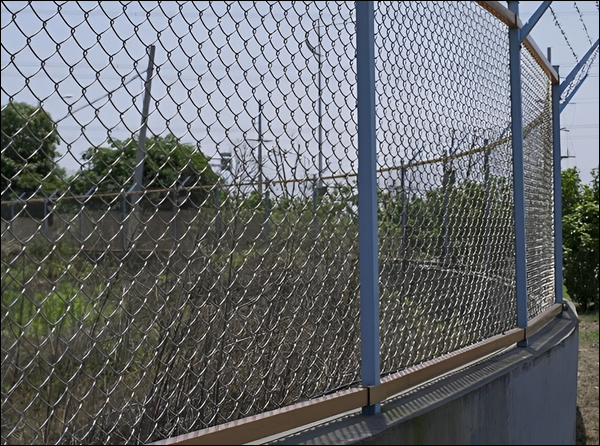
Primary Security Line (PSL) Chain-Link Fence Project for airports is a critical infrastructure initiative designed to enhance security by establishing a robust and reliable perimeter around sensitive airport areas. This type of fence is characterized by its durable construction, typically made from galvanized steel, ensuring long-lasting protection against unauthorized access. The PSL chain-link fence is ideal for creating secure boundaries while maintaining visibility, allowing security personnel to monitor the area effectively. It is widely used for securing airfields, terminals, and restricted zones, providing a physical barrier that deters intrusions and enhances safety protocols. The project involves the installation of high-quality, corrosion-resistant chain-link fencing that meets industry standards, offering a versatile and cost-effective solution for airports to safeguard both their facilities and operations.


Materials
- Fabric: Woven with 9-gauge galvanized steel wire in a 2-inch (50 mm) mesh, meeting ASTM A392, Class 2.
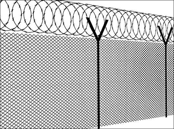
- Razor Wire: Concertina razor wire, 2-strand 12-1/2 gauge zinc-coated, conforming to ASTM A121, Class 3, Chain Link Fence Grade.
- Posts, Rails, and Braces:
Galvanized tubular steel pipe (ASTM F-1043 or F1083): with Type A coating, or with Type B external and Type B or D internal coatings. For aluminum alloy fabric: Posts, rails, and braces shall be made of aluminum alloy or composite. Other materials (except galvanized steel and aluminum alloy) must pass a 1,000-hour salt spray test (ASTM B117) with a maximum of 5% red rust externally and 650 hours with a maximum of 5% red rust internally. - Wire Ties and Tension Wires: Wire ties shall match the fabric material and coating. Top and bottom tension wire: 7-gauge marcelled steel wire, coated to match the fabric, conforming to ASTM A824.
- Miscellaneous Fittings and Hardware: Commercial-grade steel or better, wrought or cast, with sufficient strength. Zinc coating shall conform to ASTM A153. Razor barbed wire support arms must withstand a 250-pound (113 kg) vertical load.
- Concrete: Commercial grade with a minimum 28-day compressive strength of 3,000 psi (17,240 kPa).
- Marking: Fabric rolls shall be tagged with base metal, coating, wire gauge, length, and manufacturer. Posts, wire, and fittings shall be identified by base metal, and coating.
Primary Security Line (PSL) Chain-Link Fence Gates
- Single, Double, and Motorized Sliding Gates: These will be measured individually for various opening lengths. The supply and installation of all posts, rails, braces, electrical grounds, tension wires, and ties will be incidental to the gate installation. The installation of three strands of razor wire, photocells, and vehicle detection loops will also be incidental to the gate installation.
- Pedestrian Gates: These will be measured individually for various opening lengths. The supply and installation of all posts, rails, braces, electrical grounds, tension wires, and ties will be incidental to the gate installation. The installation of three strands of razor wire will also be incidental to the gate installation.
- Aluminum Swing Gates: These will be measured individually for various opening lengths. The supply and installation of all aluminum posts, rails, braces, electrical grounds, tension wires, and ties will be incidental to the gate installation. The installation of three strands of razor wire will also be incidental to the gate installation.
- Cross-Sectional Dimensions: Cross-sectional dimensions shall not deviate from the design by more than 6 mm.
- Vertical Centerline: The vertical centerline shall not be out of plumb by more than 6 mm.
- Longitudinal Dimensions: Longitudinal dimensions shall not deviate from the design by more than 6 mm per 3 meters of gate opening.
- Anchoring Location: The supplier shall specify the location of anchoring.
- Function: The gate is a modular, cantilevered vehicular access gate designed to close access routes and regulate traffic flow.
- Construction: The gate features a modular, lightweight construction with a tensioned design.
- Operation: The gate operates with low resonance by utilizing guide wheels mounted on structural portals.
- Control System: The gate utilizes microprocessor electronic control powered by a single-phase 240V power supply.
- Color Options: Standard and optional color combinations are available.
- Access Control: The gate supports various access control options, including:
- Magnetic card reader
- Manual key switch
- Electronic key
- Pushbutton
- Hand-held transmitter
- Operation Activation: The gate is activated by a vehicle detector unit with a sensing loop.
- Attention Devices: The gate includes the following attention devices for improved safety:
- Traffic lights
- Flashing lights
- Audible warning signals (This combines 2 & 3)
Jersey Barrier Specifications
1. Permissible Dimensional Tolerances
- Cross-section: Variations from design shall not exceed 6 mm. Vertical centerline deviation shall not exceed 6 mm.
- Longitudinal: Dimensional variations shall not exceed 6 mm per 3 meters of barrier section and shall not exceed 20 mm per section.
- Anchorage: Location as specified by the supplier.
2. Physical Requirements
- Compressive Strength: Per ASTM C39. Average daily test results shall meet or exceed the specified design strength.
- Concrete Finishing: Shall be uniform and comparable to the steel form finish.
- Lifting Devices: Not to be cast into barrier sides.
- Anchorage: Dowels, keyway joints, or interlocking devices as specified by the Airport Authority or Consultant.
- Steel Reinforcement: Designed for handling, delivery, and placement. Minimum concrete cover is 50 mm. Reinforcement cage shall maintain shape during casting.
- Concrete Design Strength: 4,000 psi (27.6 MPa) at 28 days.
- Air Entrainment: 5% ± 1% as per ASTM C173 or C231.
3. SUBMITTALS
- Chain-Link Fencing Components
- Accessories
- Gate Operator
- Fabric
- Posts
- Braces
- Framing
- Rails
- Tension Wires
4. EXECUTION
4.1 CLEARING FENCE LINE:
- Remove all trees, brush, stumps, logs, and debris within 500 mm of the fence centerline.
4.2 INSTALLING POSTS:
- Set posts on concrete barriers at specified dimensions and depth.
- Spacing: No more than 3 meters.
- Set posts at least 400 mm into the concrete barrier.
- Ensure posts are plumb, aligned, and at the required grade.
- After setting, fill the remaining hole with grout (1:2 cement-sand mix).
- Do not install materials or disturb posts for 7 days after footing completion.
4.3 INSTALLING BRACES:
- Install horizontal brace rails with diagonal truss rods and turnbuckles at terminal posts and where alignment changes exceed 30 degrees.
4.4 INSTALLING FABRIC:
- Attach wire fabric securely to posts and braces as shown on the plans.
- Ensure wire is taut and installed at the required elevations.
- Maintain a 25-100 mm clearance between the bottom of the fabric and the top of the concrete barrier.
- Grade the ground for a neat appearance.
